
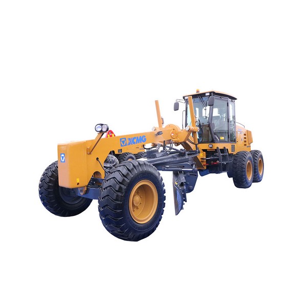
What does a motor grader do?
What does a motor grader do? Earth-moving machinery that uses a scraper to level the ground. The scraper is installed between the front and rear axles of the machine and can be lifted, tilted, rotated, and extended. The action is flexible and accurate, the operation is convenient, and the leveling site has high precision. It is suitable for constructing roadbeds and pavements, building side slopes, excavating side ditches, mixing pavement mixtures, sweeping snow, pushing bulk materials, and carrying out dirt roads and ditch. Maintenance of gravel roads.
The scope of application of the motor grader
Motor graders are the main machinery used for shaping and leveling operations in earthworks and are widely used in large-area ground leveling operations such as highways and airports. The reason why the grader has a wide range of auxiliary work capabilities is that its moldboard can complete 6 degrees of movement in space. They can be carried out individually or in combination. The grader can provide sufficient strength and stability for the roadbed in the construction of the roadbed. Its main methods in subgrade construction are leveling, slope brushing, and embankment filling. A grader is a high-speed, high-efficiency, high-precision, and multi-purpose earthmoving machine. It can complete large-scale ground leveling and ditching, scraping, bulldozing, snow removal, loosening, compaction, cloth, mixing, auxiliary equipment, and wasteland reclamation for large areas such as highway important content fields and farmland. It is important equipment in the construction of national defense engineering, mine construction, road construction, water conservancy construction, and farmland improvement. The roadbed is the foundation of the road surface and an important part of highway engineering. The roadbed bears the traffic load from the road surface and is the supporting structure of the road surface. It must have sufficient strength, stability, and durability. Depending on the terrain, highway subgrades generally take the form of embankments and cuttings.
The history and development of motor graders
The original grader can be traced back to America at the end of the 19th century. Since the 1920s, in nearly 80 years of development, motor graders have experienced low speed to high speed, small to large, mechanical manipulation to hydraulic manipulation, mechanical shifting to power shifting, mechanical steering to hydraulic power steering, and then to Full hydraulic steering and the evolution of the whole frame to the shovel frame. The reliability, durability, safety, and comfort of the whole machine have been greatly improved. With the development of technology, the development, and application of machinery manufacturing and hydraulic technology. With their combined application in construction machinery products, high-tech represented by modern microelectronics technology is more and more commonly used to transform the traditional structure of construction machinery products. The transplantation and application of mature technology have greatly promoted the further improvement of the comprehensive technical level of motor graders. Motor graders have developed to the level of self-leveling. Automation has become the development trend of motor graders. Therefore, motor graders have also been widely used. In particular, the M-series motor graders launched by Caterpillar have revolutionary integrated the machine’s control system on an operating handle similar to an aircraft joystick, allowing operators to complete construction tasks more intelligently.
Structural features of the motor grader
The development and expansion of grader products must not only meet the work adaptability of different working conditions but also maintain the maximum versatility (or interchangeability) of parts and components with the basic type, which brings great benefits to the use and maintenance of the majority of users. Great convenience. The crawler motor grader is mainly composed of an engine, transmission system, working device, electrical part, cab, and hood. Among them, the mechanical and hydraulic transmission system also includes hydraulic torque converter, coupling assembly, planetary gear power shift transmission, central transmission, steering clutch and steering brake, and final drive and travel system. The power take-off mechanism drives the working pump in the hydraulic system of the working device, the speed change pump of the variable torque variable hydraulic system, and the steering pump of the steering brake hydraulic system using gear transmission and spline connection; the sprocket represents the final drive mechanism of the second spur gear transmission (Including left and right final drive assemblies); Track shoes include the crawler assembly, trolley frame and suspension assembly including the traveling system.
Motor Grader’s Drive System
Motor graders use mechanical transmission or hydro-mechanical transmission systems with hydraulic torque converters, and a few use hydraulic transmission systems.
Torque Converters for Motor Graders
The pump wheel in the pump wheel assembly is connected with the drive shell by bolts, and the drive gear is connected with the drive shell by the bolts. The drive gear is directly inserted into the engine flywheel ring gear, so the pump wheel rotates with the engine. The guide wheel is connected with the guide wheel hub by bolts, the guide wheel hub is connected with the guide wheel seat through splines, and the guide wheel seat is connected with the torque converter shell through bolts, so the guide wheel and the torque converter shell together do not rotate. The turbine and the turbine hub are riveted together with rivets, and then connected to the turbine output shaft through splines, and the turbine output shaft is connected through splines and couplings to transmit power to the subsequent transmission system. The pump wheel rotates with the engine, inputting the power, the guide wheel does not rotate, the turbine rotates, and the power is output. The three are independent of each other, and the gap between the wheels is about 2mm. The pump impeller, turbine, and guide wheel are composed of many blades, which are called cascades. The blades are composed of curves and have complex shapes. When the torque converter is working, the blade cascade needs to be filled with oil. When the pump wheel rotates at a high speed, the oil in the pump wheel blade cascade flows outwards along the curved surface under the action of centrifugal force and shoots towards the outlet of the blade cascade. The outlet of the turbine blade cascade then flows centripetally along the curved surface of the turbine blade cascade, and then shoots from the outlet of the turbine blade cascade to the inlet of the guide vane cascade, and flows back to the pump wheel through the guide wheel cascade. The circular space composed of a pump wheel, turbine, and guide wheel blade cascade is called a circulating circle. Due to the design of the curved shape of the turbine blade cascade, it is determined that the turbine and the pump impeller rotate in the same direction. In this way, the oil in the circulating circle of the torque converter cascade rotates in the circulating circle on the one hand, and rotates with the pump impeller and turbine, on the other hand, thus forming a complex spiral motion, in which the energy is transferred from the pump to the pump. wheel to the turbine. The load of the turbine is determined by the load of the motor grader. The load of the motor grader is transferred from the blade to the track travel system, to the final drive, steering clutch, central drive, transmission, and coupling assembly, and finally to the torque converter turbine.
When the load of the turbine is small, its rotation speed is fast; when the load is large, the rotation speed is slow. When the motor grader cannot move due to overload, the speed of the turbine also drops to 0, which becomes the braking state of the turbine. At this time, because the turbine stops rotating, the oil ejected from the pump impeller cascade will pass through the turbine cascade with the greatest impact and rush to the guide wheel, and is converted into pressure in the non-rotating guide wheel cascade, and the pressure is counter-pressured toward the guide wheel. The turbine increases the torque of the turbine, and the increased torque is consistent with the rotation direction of the turbine. At this time, the output torque of the turbine is the largest, which is 2.54 times the torque of the pump impeller. As the load increases, the speed of the turbine gradually decreases, and the torque gradually increases, which is equivalent to a continuously variable transmission gradually reducing the speed and increasing the torque. This continuously variable torque performance, combined with an easy-to-maneuver and less geared planetary powershift transmission, provides the grader with excellent traction. Torque converters work hydraulically. When the oil flows in the cascade, due to impact and friction, energy will be consumed and the oil will be heated, so the transmission efficiency of the torque converter is low. The best torque converter at home and abroad has a maximum efficiency of 88%. When the turbine of the torque converter stops rotating due to the overload of the motor grader, all the energy transmitted by the pump wheel is converted into heat and consumed. At this time, the efficiency of the torque converter is 0. To improve the transmission efficiency of the torque converter, it is necessary to master the load of the grader, so that the turbine has an appropriate speed and the grader has an appropriate speed; that is, when the grader cannot move due to excessive load, it should be reduced in time. load, lift the blade, or shift from II to me. According to the structure and working principle of the torque converter, the oil will leak and heat up when the torque converter is working. This requires that oil should be replenished inside the torque converter in time, and the hot oil should be replaced and cooled to form a cycle.
Grader clutch
There are 5 clutches. The cylinder blocks of the 1st to 4th clutches are all bolted to the end cover, and they do not move. When the oil between the cylinder block and the piston is filled with pressure oil, the pressure oil builds up oil pressure and pushes the piston to compress the friction plate under the seal of the oil exceeding the plan, so that the ring gear can be fixed. The structure of the No. 5 rotary locking clutch is rather special. It does not have a planetary mechanism, and it rotates as a whole when it works. When supplying oil to the rotary cylinder, the oil must be supplied to the central shaft first. When working, the pressure oil enters the rotary oil cylinder through the oil passage in the fixed casing 19 of the fifth clutch and pushes the piston to work. To prevent leakage, seal with a rotating sealing ring. After the work is completed, due to the continuous rotation of the rotary oil cylinder, the centrifugal force is thrown outward and cannot be discharged through the oil supply passage, which will increase the wear of the friction plate. To solve this problem, discharge in the rotating oil passage will increase the wear of the friction plate. To solve this problem, a steel ball check valve is added to the rotating oil cylinder body. Under the action of the pressure oil, it seals the oil hole to build up oil pressure. When the oil supply stops, it will throw away and open the oil return hole to return Oil.


Thank you for explaining just what a grader does. Graders are commonly used in the construction and maintenance of dirt and gravel roads. In constructing paved roads, they prepare a wide flat base course for the final road surface. They also prepare the surface for drainage, which is important for maintaining a clean and healthy roadway. Graders also are used to grade the road for a slope.
Motor graders play a crucial role in road construction and maintenance, and it’s fascinating to learn how they help achieve the smooth and level surfaces we drive on every day. The ability to grade and shape the terrain with such precision is impressive, and I now have a better understanding of the various applications for motor graders.
Hello, I think your site might be having browser compatibility issues.
When I look at your blog in Opera, it looks fine but when opening in Internet Explorer, it has some overlapping.
I just wanted to give you a quick heads up! Other then that, fantastic blog!